
Impedance matching is an engineering concept that describes how well an energy source is adapted to its load. In electrical systems, a source such as an amplifier has an internal opposition to current flow, its internal impedance, and the load, such as an antenna, a cable, or another circuit, has its own impedance. When these two are chosen so that they appear effectively identical at their interface, energy transfer is efficient and wave reflections are minimized. In classical maximum power transfer terms, this means that the numerical value and frequency dependence of the load impedance closely mirror those of the source. In reflection terms, matching corresponds to a situation in which the junction between source and load sends essentially none of the incident wave back and almost everything continues into the load. If there is a substantial mismatch, a significant part of the wave is reflected toward the source, less power reaches the load, and the source must work harder to achieve the same useful output. The same reasoning applies in acoustics and mechanics: whenever waves move between different media, the severity of the mismatch at transitions determines how much energy is transmitted and how much is reflected or dissipated locally.
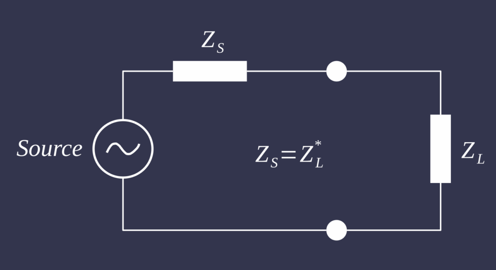
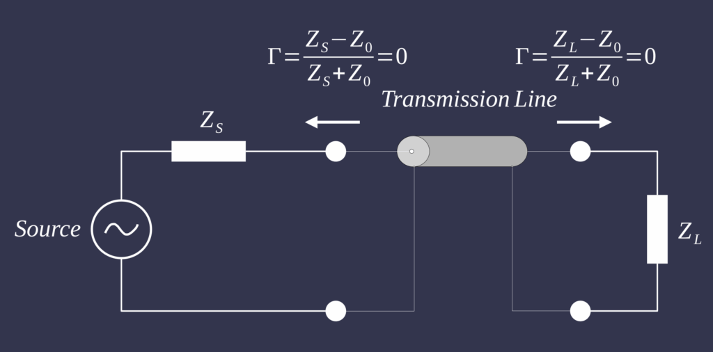
This behaviour can be represented in two different circuit descriptions, depending on the physical scale. In a lumped parameter circuit, all resistances, capacitances, and inductances are treated as if they are concentrated in discrete components see first figure. In this setting, the classical maximum power transfer problem is solved by choosing the load impedance to match the internal impedance of the source, so that no part of the circuit forms a dominant bottleneck for energy flow. Signals are assumed to propagate so quickly that time delays along wires can be ignored, and the entire system can be described by ordinary time-dependent equations. This is appropriate when the physical dimensions of the system are small compared with the wavelength of the signals of interest. A transmission line model, illustrated in the second figure by inserting a finite line between ZS and ZL, treats resistance, capacitance, inductance, and leakage as continuously distributed along the line. Voltage and current then depend on both position and time, and one must account explicitly for finite propagation speed and reflections whenever the line encounters an impedance change. For many low-frequency design problems, a lumped circuit is sufficient, but when wave propagation, resonance, and reflection become important, a transmission line description is required to speak meaningfully about impedance matching.
The cardiovascular system can be interpreted through the same lens, both in the systemic circulation and in the pulmonary circulation. Each ventricle acts as a pulsatile source that generates pressure and flow, and each arterial bed, systemic or pulmonary, is its load, characterized by overall resistance, compliance, and wave propagation properties. At the entrance to the arterial tree, in the aorta or pulmonary artery, the combined behaviour of all downstream vessels can be summarized as an input relationship between pulsatile pressure and pulsatile flow. In a lumped parameter view, the arterial bed is represented by a small number of elements, for example a Windkessel model with a total resistance and a total compliance, and afterload is described as an effective, time-varying load against which the ventricle ejects. In a transmission line view, the large arteries are treated as elastic tubes that support travelling waves; local changes in diameter or stiffness act as impedance steps, and the pattern of forward and reflected waves along these tubes determines the pressure and flow signals that the ventricle actually experiences.
If the arterial properties are reasonably matched to the ventricle in either representation, ejection occurs with relatively low wasted energy and moderate wall stress. The forward pressure and flow waves generated by the ventricle are then largely transmitted into the vascular tree, while reflected waves are limited in size and arrive at times in the cardiac cycle that do not excessively raise late systolic pressure. With aging, vascular remodelling, or disease in either the systemic or pulmonary circulation, large arteries often stiffen, geometry changes, and small-vessel resistance rises. These changes create impedance mismatches: reflections become stronger and occur earlier in systole, the effective afterload rises, and the ventricle operates further away from its matched region, where it would otherwise deliver flow more efficiently. In this sense, impedance matching provides a unifying language to describe how well the heart, as a source, is adapted to its systemic and pulmonary arterial loads, whether we choose to look at them through simplified lumped models or through the more detailed perspective of wave propagation along transmission lines.
References
- Abel F. L. (1971). Fourier analysis of left ventricular performance. Evaluation of impedance matching. Circulation research, 28(2), 119–135. https://doi.org/10.1161/01.res.28.2.119
- Piene H. (1984). Impedance matching between ventricle and load. Annals of biomedical engineering, 12(2), 191–207. https://doi.org/10.1007/BF02584230